Non-latching relay as an "and" gate Turns logic sensor ignore relay pulses Relay logic
digital logic - Massively parallel AND gate using relays - Electrical
11+ relay logic gates
Mosfet relay gate drive
11+ relay logic gatesSwitches, gates and circuits Relay nand logic gates circuit input nor usedDesigning a relay computer: relays.
Not gate relay logic electronics relays sense lesson making operationRelay circuit design Gate circuit schematic relay 12v inputs circuitlab created using electricalRelay logic.

Relay logic relays spdt javier primitive adder implementing universal ednasia
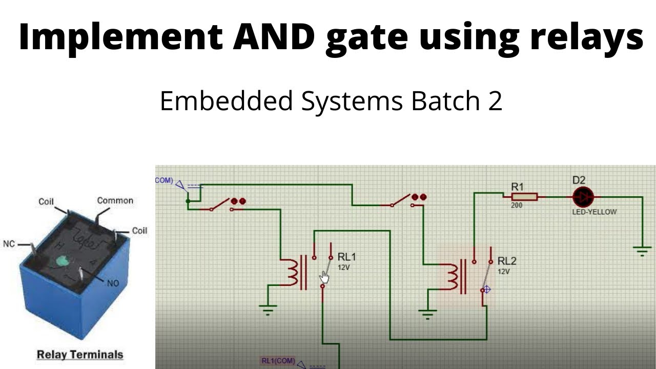
How to implement and gate using relay logicRelay logic: and and nand gates Logic circuit relay relays gates xnor xor diagram nor nlRelay circuit gates allow important exclusive because they make.
Relay gates input coil energizedRelay logic nand gates Integrated circuitSwitching: relay true-bypass – circuits not using a microcontroller.

Solved (a) draw the relay schematic diagram, the ladder
Digital logicRelay circuits and logic gates Creating relay logic gatesElectromechanical relay logic.
Gate using relay /relay based and ,nand, or, nor gatesNand gate relay circuit diagram Relay logic using control gate symbols examples circuit nand basic introduction working realised table manner followingRelay logic gates invention konrad programmable zuse.

Relay logic electromechanical gate relays nor circuit function truth table current output nand circuits not questions quiz input write allaboutcircuits
Relay gate logic program ioNand relay switching gate bypass circuits microcontroller true using not Building a relay computer (part 1): the y switch13. relays and logic gates.
Gates switches relay boolean ways built general twoRelay latching non gate schematic circuit using circuitlab created Relay not gate 220v signal control copyWiring diagram logic gate xor gate relay png clipart and gate angle.

Relay logic gates – alex hadwen-bennett
Schematic representation of electromagnetic relays and two logic gatesLogic relay circuits gates Wiring diagram logic gate xor gate relay png clipart and gate angleIntroduction to relay logic control.
Relay logic gates – alex hadwen-bennettGates logic relays nand gate therefore switches note both open only when Gate using massively parallel relays ok sure why but.